Build your own Gumstix Powered Astromech Droid with the AeroCore 2 + COM and iRobot Create 2
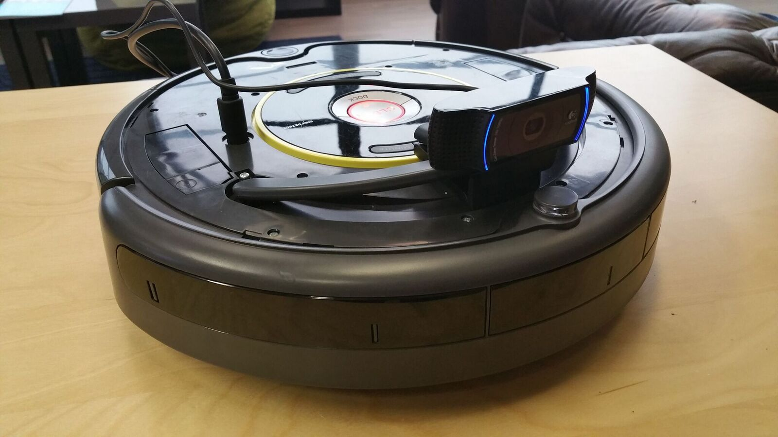
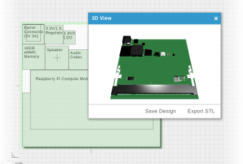
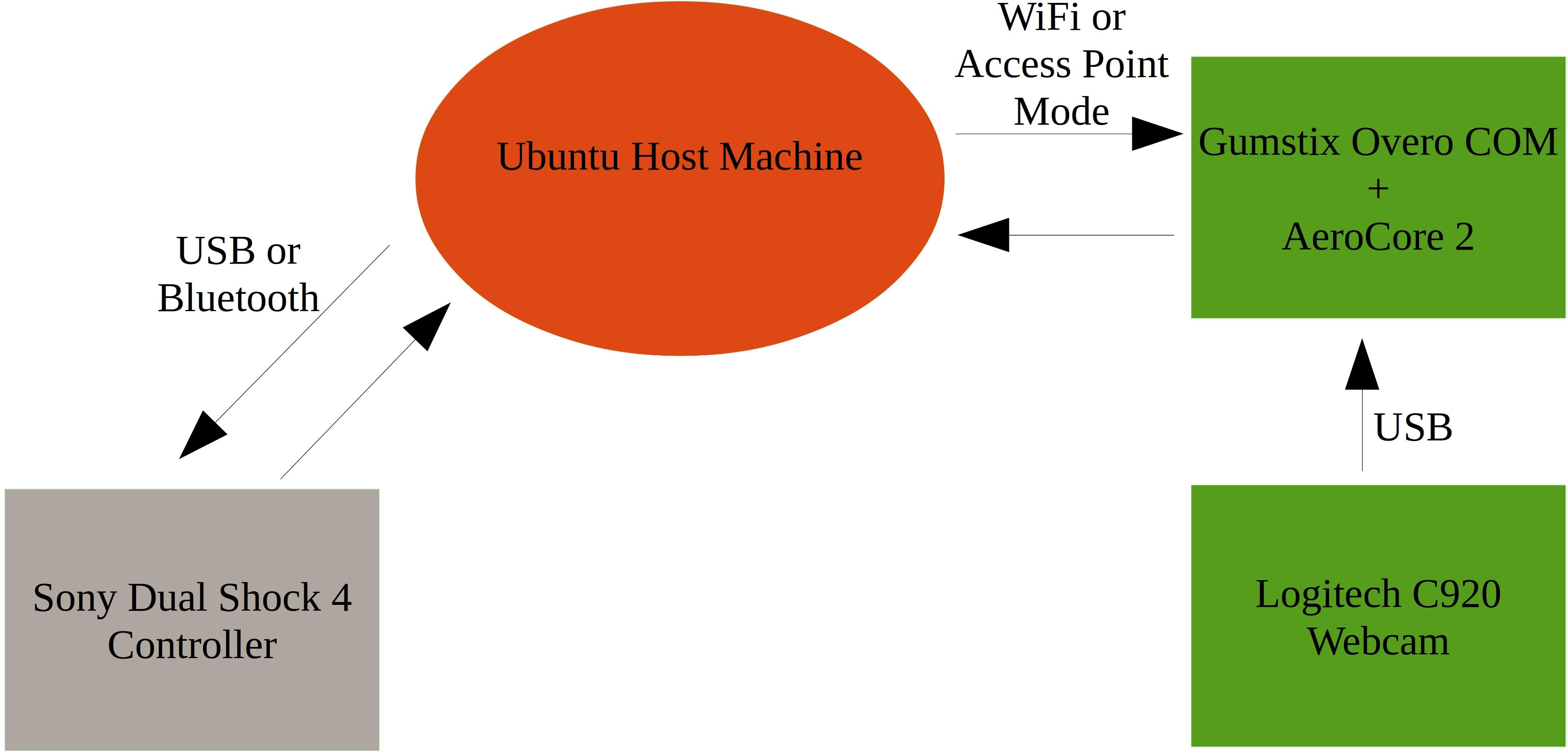
This tutorial will be a new way to control an iRobot Create 2 with Gumstix products, featuring the Gumstix AeroCore 2 for Overo. We’ll control the iRobot Create 2 with a Sony DualShock 4 controller connected to an Ubuntu desktop machine. The Ubuntu machine will forward a command stream to the Overo + AeroCore 2 over a WiFi network, or the Overo in Access Point mode. The Overo will stream a live video feed from the Logitech C920 webcam back to the Ubuntu machine. All the components fit nicely in the stock dust bin, or 3D printed one from the first iRobot Create 2 Tutorial.
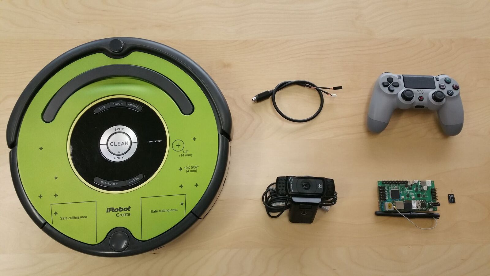
Hardware:
- Gumstix AeroCore 2 for Overo (or DuoVero)
- Gumstix Overo Airstorm-Y (or DuoVero)
- U.FL antenna
- Gumstix Create 2 Cable
- 2GB+ MicroSD card (8GB if you’re using the dd’able image)
- iRobot Create 2
- Sony DualShock 4 controller
- Logitech C920 USB webcam
- A host machine running desktop Ubuntu
Software
- Host and target source files for controlling the Create 2
- Gumstix u-boot repo
- Gumstix Yocto layers
- SD card formatting script
- ds4drv
- Source Files or dd’able image
Flashing the dd’able Image
If you would like to get moving right away, you may download the dd’able image above and flash it straight to your 8GB microSD card (note this image is for the Overo COM, you will have to continue with the tutorial if you are doing this on another COM):
Extract the .img file and dd it onto your 8GB microSD card (replace /dev/sdc with the path to your microSD card):
unxz ac2_overo_create2.img.img.xz
sudo dd if=./ac2_overo_create2.img.img of=/dev/sdc bs=4M
Now insert the microSD card into your Overo, put your Overo on your AeroCore 2 and power the board!
Give the COM a couple minutes to boot up, and you should be able to connect to its access point. The default name is overo_create2_accesspoint. You can edit this in /etc/hostapd.conf
Once you have connected to the access point, ssh into the COM and jump to “Preparing the Host” to prepare the host packages and start roving!
NOTE: If after 5 minutes you still do not see the access point up, move the uEnv.txt on the boot/ partition of the microSD card to somewhere safe and follow the steps in “Prepare the Target”. You will have to place uEnv.txt back in boot/ later.
Plan of Attack
The Gumstix Create 2 cable breaks out the battery voltage from the Create 2 as well as the RX and TX lines from the serial interface. This makes for a much nicer setup, removing the need for batteries or long cables.
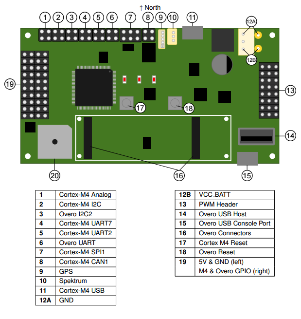
To communicate with the Create 2’s serial interface, we will need to use a UART connection from the Overo that has been broken out on the AeroCore 2. We’ll need to refer to the following documents:
AeroCore 2 User Manual
AeroCore 2 Schematics
The pictures below show how you need to connect the RX and TX lines to the AeroCore 2’s Header 6. Make sure the brown wire is connected to TX, and Orange is connected to RX on the Overo UART.
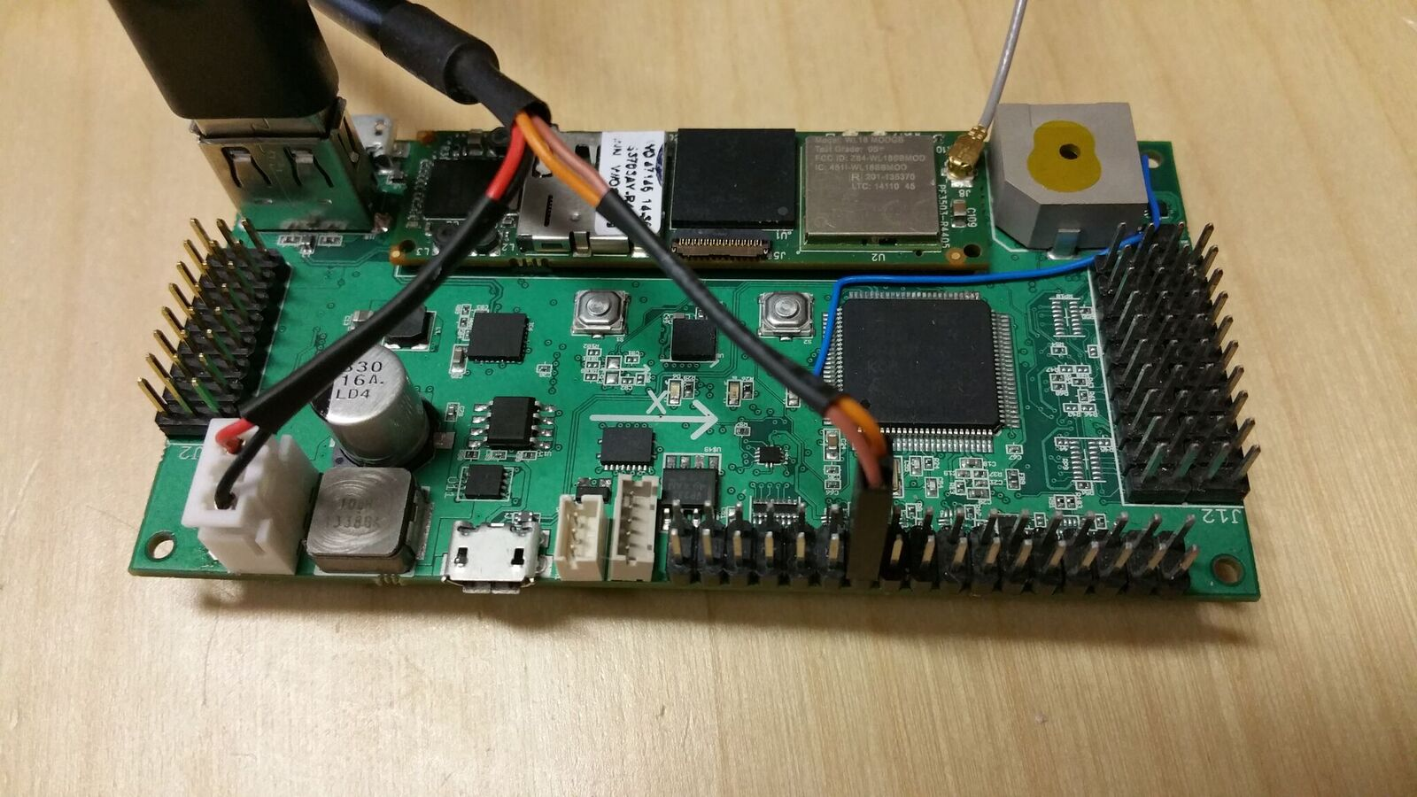
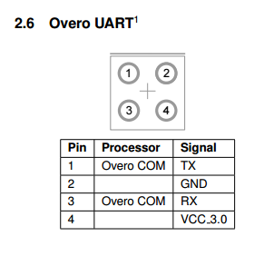
You may connect the JST connector now, which will power the AeroCore 2 and COM. It is best to leave the UART headers unconnected for now, as you will see.
The AeroCore2 schematics:
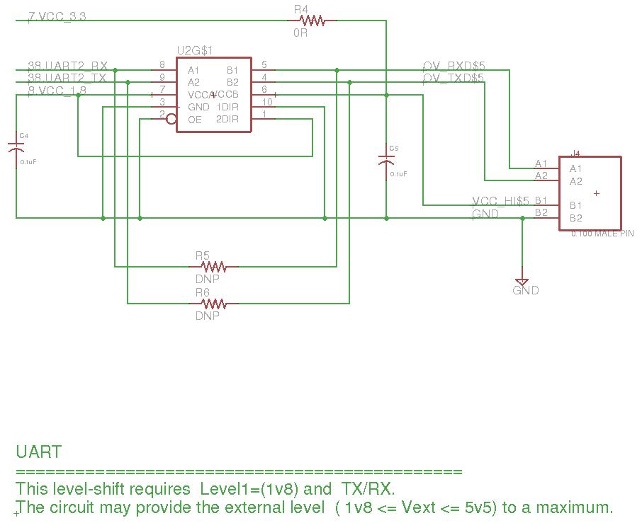
The level shifter for the Overo UART header on the AeroCore 2.
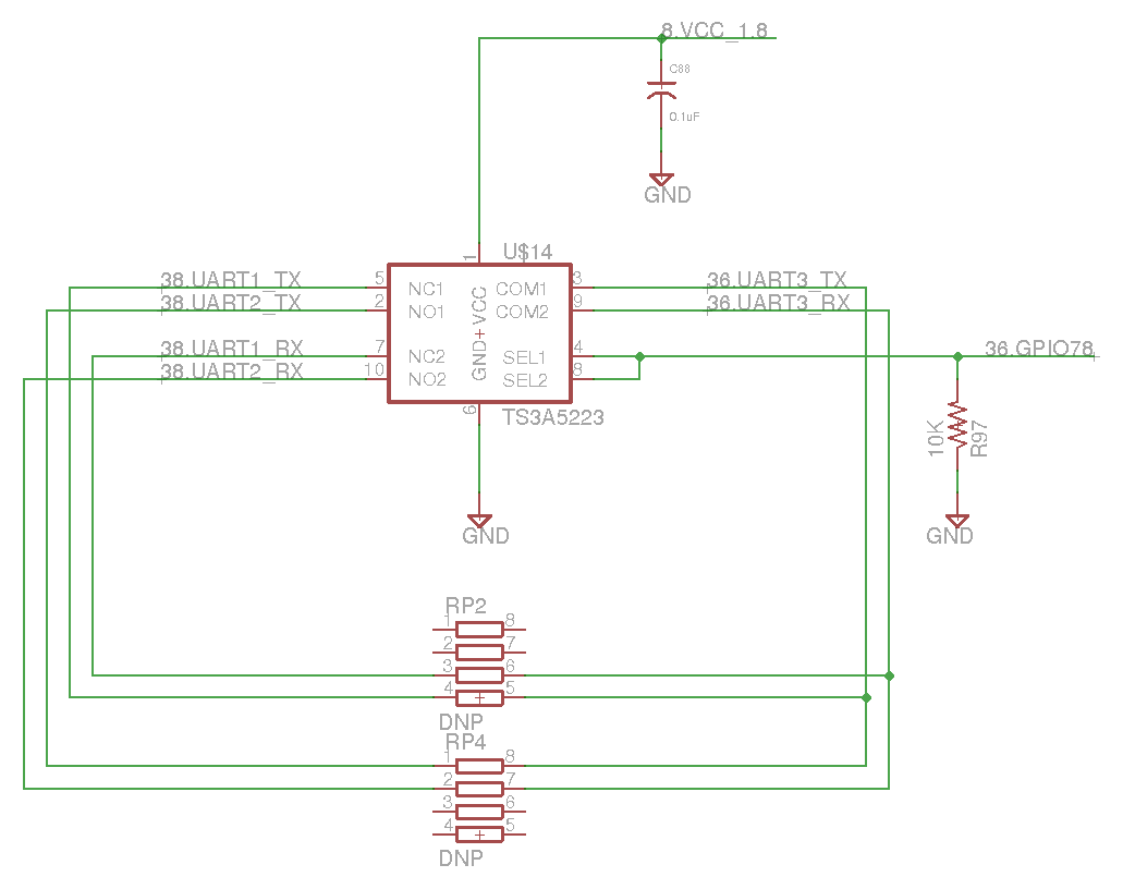
The UART 2 comes from the output of an analog switch (TS3A5223) which takes the Overo’s UART 3 as input and its GPIO78 to select what the output will be. If you do a search for “38.UART1_TX” you’ll find that this is the default serial console for the Overo which is broken out to the microUSB port on the AeroCore 2 through an FTDI USB to UART chip.
This means that in order to use the UART header on the AeroCore 2 we won’t be able to get serial access to our Overo through the microUSB port. Which won’t be too much of a problem, since the Overo’s wireless capabilities allow us to connect to it wirelessly over SSH. However, this will require us to remux some of the pins on the Overo and set up the wireless networks over the serial console and establish an SSH connection before we disconnect the serial console and route the UART bus to the AeroCore 2 headers.
Summary of our Plan of Attack:
- Build an image with the necessary packages using the Yocto Project
- Build a u-boot image with properly mux’d pins
- Format and populate SD card
- Prepare target
- Prepare host
- Start roving!
Build an Image with the Necessary Packages using the Yocto Project
NOTE: you may also use an exiting Yocto built image (or one from http://catalina.gumstix.com) and ‘smart install’ the missing packages
If you haven’t done so yet, follow the instructions from the Gumstix Yocto Manifests page linked above. Return here after step 4, we’ll want to add some packages to our recipe before we bitbake.
Open up yocto/poky/meta-gumstix-extras/recipes-images/gumstix/gumstix-console-image.bb and add the following packages:
GSTREAMER_INSTALL = " \
  gstreamer1.0 \
  gstreamer1.0-plugins-good \
  gstreamer1.0-plugins-bad \
"
CREATE2_PYTHON_INSTALL = " \
  python-pyserial \
  python-subprocess \
"
You’ll also need to add these two variables to IMAGE_INSTALL in order to have the packages included, it should look like:
IMAGE_INSTALL += " \
  ${FIRMWARE_INSTALL`} \
  ${SYSTEM_TOOLS_INSTALL} \
  ${DEV_TOOLS_INSTALL} \
  ${NETWORK_TOOLS_INSTALL} \
  ${MEDIA_TOOLS_INSTALL} \
  ${GRAPHICS_LIBS} \
  ${UTILITIES_INSTALL} \
  ${GSTREAMER_INSTALL} \
  ${CREATE2_PYTHON_INSTALL} \
"
Now return to the build directory and run bitbake!
$ cd yocto/build
$ bitbake
Build a u-boot Image with Properly Mux’d Pins
NOTE: you can skip this part and use the supplied MLO and u-boot.img in the supplied files.
If you haven’t done so already, clone the Gumstix u-boot repo following the instructions on the wiki tab linked above, return here before building the binaries as we’ll need to make some changes before building.
Referring to the AM3703 datasheet, do a search for “gpio_78”. You will see that default mode 0 is “dss_data8”, if we want this pin to behave as “gpio_78”, we’ll need to remux it to mode 4. To do that we need to edit u-boot/board/overo/overo.h (if you are using another COM or SBC, pick the appropriate header file for your board). We only need to make one change to line 63, and change the mux mode for “DSS_DATA8” from M0 to M4:
/* change the following */
MUX_VAL(CP(DSS_DATA8),		(IDIS | PTD | DIS | M0)) /*DSS_DATA8*/\

/* to this */
MUX_VAL(CP(DSS_DATA8),		(IDIS | PTD | DIS | M4)) /*GPIO_78*/\
And we’re good to go! Move back to the head of the u-boot repo and get building:
$ cd u-boot
$ make ARCH=arm CROSS_COMPILE=arm-linux-gnueabi- all -j4
Format and Populate SD Card
Download the mk2partsd script linked above and run it with sudo privileges on your unmounted microSD card:
$ umount /media/${USER}/*
$ sudo ./mk2partsd /dev/sd*
After that is complete, reinsert your microSD card and you should see a boot and a rootfs partition. Copy the MLO and u-boot.img files that you have just built to the boot partition of the microSD card.
$ cd u-boot
$ cp MLO u-boot.img /media/${USER}/boot/
After your Yocto Project has finished bitbaking, extract the filesystem tarball to the rootfs partition:
$ cd yocto/build/tmp/deploy/images/overo
$ sudo tar xvaf gumstix-console-image-overo.tar.bz2 -C \
/media/${USER}/rootfs --strip-components=1 && sync
Next you’ll need to extract the target_files.tar.gz to the microSD card’s rootfs as well:
$ sudo tar xvaf target_files.tar.gz -C \
  /media/${USER}/rootfs/home/root
And that’s it for the target side, insert the microSD card, connect power to the AeroCore 2, as well as a microUSB cable to the microUSB port by the COM and open a serial connection to the COM using GNU Screen or any other terminal emulator, login with user root:
$ screen /dev/ttyUSB* 115200n8
Prepare the Target
After you have established a wired serial connection to the COM, edit /etc/wpa_supplicant/wpa_supplicant-wlan0.conf to configure a WiFi connection
You may leave the file as is if you are connecting to a known open network. If you are connecting to a protected network, fill out ssid and psk and uncomment the second network node, then enable WiFi:
# systemctl enable wpa_supplicant@{wlan0}
Next edit /etc/hostapd.conf, you may change the SSID to anything you like, and/or uncomment the other variables to add security to your network, then enable hostapd (access point daemon) and reboot:
# systemctl enable hostapd
# reboot
Give your COM a minute to boot up and then check if all the wireless connections are up and running:
# ifconfig
ap0		Link encap:Ethernet HWaddr . . .
		inet addr:192.168.2.1 . . .
		. . .
lo		Link encap:Local Loopback
 		inet addr:127.0.0.1 . . .
		. . .
wlan0		Link encap:Ethernet HWaddr . . .
		inet addr:192.168.1.x . . .
		. . .
If you see three (or two if you didn’t configure wlan0) network configurations with IP addresses (inet addr) then you’re good to go! If ap0 is configured, you should see a WiFi network with the same name as the ssid value you set in /etc/hostapd.conf, connect to this network, and establish an SSH connection to your COM from your host machine:
$ ssh root@192.168.2.1
Now that we have established a wireless connection, unplug the microUSB cable from the AeroCore 2 and lets get the UART bus onto the AeroCore 2 headers. To do this, we’ll copy the text file called uEnv.txt in the target_files we extracted earlier to the microSD’s boot partition. The text file will instruct u-boot to move the serial console off of ttyO2 (UART3) (will vary if you are using a DuoVero) and choose to boot with a device tree that doesn’t utilize DSS_DATA8:
Mount the boot partition on your COM, copy uEnv.txt over, and reboot:
# mount /dev/mmcblk0p1 /mnt
# cp target_files/uEnv.txt /mnt
# reboot
SSH back into your COM when it has finished booting and you can connect to the access point again.
Prepare the Host
We are nearly ready to start roving! Install the ds4drv driver by chrippa on your Ubuntu machine, and connect your Sony Dualshock 4 controller to the machine.
Start Roving!
First change the host parameter in c920_stream in target_files to your Ubuntu machine’s IP address.
On your COM, start the Python script with maximum un-niceness:
# cd target_files
# nice --20 python udp_robot_server.py
On your Ubuntu Machine open two tabs:
$ cd host_files
$ ./c920_stream_receive
Change HOST in udp_joy_parse.py to your COM’s IP address (probably 192.168.2.1 if using APM):
Start the joystick parser (you will need to enter your password as ds4drv is called with sudo):
$ python udp_joy_parse.py
The controls at the moment are the following (you may edit the Python scripts as you wish of course):
- Right and left analog sticks control the right and left wheels like a tank.
- The default max speed is 50mm/s, you can increase this (50mm/s increments) with R1, and decrease with L1.
- The controller’s trackpad is mapped to the Create 2’s speaker. Touching the trackpad plays a note defined by the x-position of your finger on the trackpad.
 RSS
RSS