Overo Series
Gumstix's product series powered by the OMAP3 applications processors (Texas Instruments) with Cortex-A8. Find the product roadmap, videos, I/O design information, 2D layout and 3D models, expansion board schematics, vibration testing results and more.
The wealth of Overo reference material is divided into categories below.
Types of COMs
| No Wireless Communication | WiFi 802.11b/g/n Bluetooth 3.0 | WiFi 802.11b/g/n Bluetooth 4.1 + BLE | |
|---|---|---|---|
| Base Model | EarthSTORM | AirSTORM-P* | AirSTORM-Y |
| PowerVR SGX C64 + Digital Signal Processor |
WaterSTORM | FireSTORM-P* | FireSTORM-Y |
| PowerVR SGX C64 + Digital Signal Processor Extended Temperature Components |
IceSTORM | IronSTORM-P* | IronSTORM-Y |
*discountied
Overo Series Overview
The Overo series packs a lot of computing power in a tiny package.
In this section, you'll be introduced to:
- The hardware of the Overo series.
- Linux and our User Wiki.
- OpenEmbedded - which is the "build environment" for writing code and developing an application using Overo products.
- Videos showing the connecting, cabling and powering up of various Overo configurations.
If you do not need an overview and just want to get started setting up your Gumstix system, then jump ahead to the "Getting started" section.
Introductory Videos
Gumstix has posted a series of videos that provides an introduction to the features and set up of several Overo configurations.
Hardware Introduction to the Overo series
The products in the Gumstix Overo series are divided into two areas:
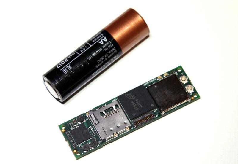
- The computer-on-module or "COMs", which are smaller than the size of your index finger.
- The dual 70-pin expansion boards which provide the connectors needed for I/O functions such as USB, power input, LCD and HDMI and more. Each expansion board is the same size or bigger than the Overo COM so that there is room for the various connectors and I/O thru-holes and perhaps to fit around the LCD panel.
Each Gumstix Overo COM can fit on every expansion board of the Overo series, except with one or two exceptions noted on the product pages at www.gumstix.com.
Despite the small size, a Gumstix Overo COM and expansion board combination performs like a full-sized, Linux computer and can be programmed to perform a wide variety of functions in almost any application area including power management, time & attendance, security, access control, information technology, location tracking, medical, aviation, robotics and education, to name a few.
Angstrom Linux has been pre-loaded on every Overo COM that has NAND (flash) memory before shipment by Gumstix.
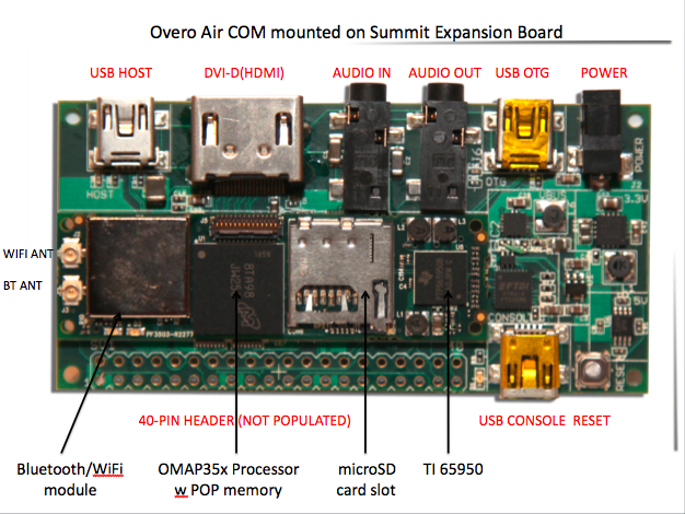
The main features of an Overo COM can include:
- TI OMAP3503/3503/3730 applications processor featuring the ARM® Cortex™-A8.
- Package-on-Package (POP) memory: 256MB or 512 MB low-power DDR RAM with no NAND / 256MB NAND or 512MB NAND
- Bluetooth / 802.11b/g wireless communications module.
- microSD card slot.
- TI 65950 Power Management IC.
- Four (4) mounting holes - one in each corner.
- 17 mm x 58 mm.
- 6 grams.
Product information for each Overo computer-on-module is posted on their respective product pages at www.store.gumstix.com. Make sure to review the information behind each tab of that product page for more technical information and product specifications.
Each Overo COM also brings a wide selection of signals to the two 70-pin connectors located on the bottom of the computer-on-module. The details of the assignment of signals and pin numbers for each of the two 70-pin connectors are posted in the this page. The signals on these pins include but are not limited to the following functions:
High Speed Data
- USB 2.0 high-speed on-the-go
- MMC (8-bit wide)
Peripheral interface signals
- 24-bit LCD signals
- Serial ports
- I2C and 1-Wire
- SPI
- GPIO
- PWM (4 from the OMAP, 2 from the TPS65950)
- 10/100 Ethernet
Analog, rest and power signals
- Stereo audio line in and headset output
- Microphone and sub-microphone input signals
- A/D (6 lx 10 bits, 2.4V maximum)
- Reset, power-on, and wake-from-sleep input
- Backup battery
A list of the expansion boards for the Overo series is available at the store.
Openly Published Schematics of Each Expansion Board
To assist customers in development of their a custom expansion board(s) compatible with and driven by an Overo COM, Gumstix makes the schematic of each expansion board available freely and without cost or licensing fees, via our website at pubs.gumstix.com.
Secure Mechanicals
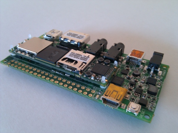
Each Overo COM and expansion board configuration can·be secured together using the 4 x 0-80 mounting holes in the corners of the Overo COM and on each expansion board and the white, plastic retaining spacers that Gumstix has made available in the accessories section of www.gumstix.com, linked here.
The spacers can be seen mounted on each corner of the Overo COM in the image below. That COM would then be turned over and connected into an expansion board, such as the Summit board shown on the left.
You may be interested in some testing performed on the Overo series by a customer using the US·Military Specification MIL-STD-810F 514.5 “Vibration” posted here.
Overo Design Overview
Connectors on each Overo COM
Every Gumstix Overo computer-on-module (COM) has the same three connectors and each connector has the same signal pattern.
2 x 70-pin connectors: J1 and J4
The bottom surface of each Overo COM has two (2) x 70-pin AVX 5602-series connectors: (J1) and (J4)
- The connector labeled J1 features the LCD, PWM and analog signals.
- The connector labeled J4 features the Extended Memory Bus and MMC signals.
- These AVX 5602-series connectors have bosses but these connectors do not have metal tabs
- Combined, these two 70-pin connectors allow for connection of any expansion board of the Gumstix Overo series or to a custom-designed expansion board mounted with mating 70-pin connectors.
- Two 70-pin connectors must be installed on each custom expansion board in order to mate that custom expansion board to a Gumstix Overo COM.
- For a low volume purchase, Gumstix sells a 10-pack of 70-pin AVX 5602-series connectors.
- For production, customers should source these 5602-series connectors directly from·their own suppliers. (Kyocera Elco part number: 245602670001829H)
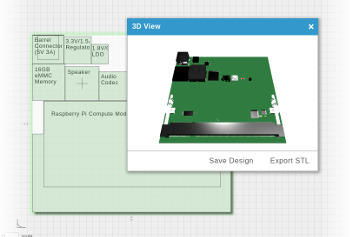
- 2D and 3D CAD drawings have been posted by Gumstix in the COMs/Overo section of pubs.gumstix.com to assist the design process of a custom enclosure or mounting assembly for an Overo-based configuration.
27-pin Connector J5
The top surface of each Overo COM has one (1) x 27-pin·Hirose FH26-27S·connector (J5):
- The connector labeled J5 features the camera control signals.
- For 0.3mm pitch flex circuit.
- Gumstix sells a flex ribbon cable for connection of a Gumstix or 3rd party camera board to this 27-pin connector.
Signals
The signals and pin numbers of Connector J1, Connector J4 and Connector J5 have been detailed within this Hardware Design / Signals and Connectors section.
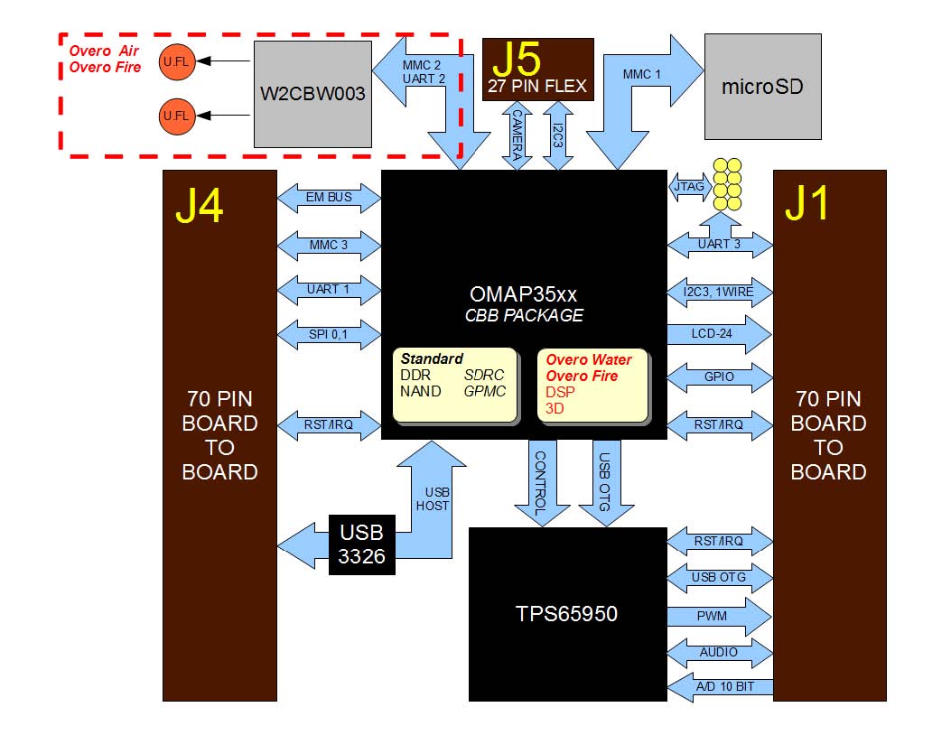
The Overo COM uses various address, signal and data lines to interface with peripherals; in general, all pins brought out to the·connectors·are available for use on expansion boards. Many signals come directly from the OMAP processor, so you can read about the function by looking at the processor data sheet. The interconnects between the OMAP chip, peripherals on the COM and the connectors is summarized in the image below. Full reference information is available in the Signals Document posted on this page.
Most signals available on these connectors are multiplexed so have several different functions as described in the OMAP3 Technical Reference Manual (see the PADCONF details in Section 7.4.4.3). Currently, the pin mux-ing is established by the u-boot bootloader; it can be changed by modifying the board/overo/overo.h file in the u-boot source code and recompiling.
Design and Production
Here you will find the models, schematics, and production references you need to create Overo-based products.
Signals and Connectors
These pages summarize the connections and interfaces to Overo COM and expansion boards.
The Overo System Reference document provides a reference for all electrical interfaces of the Overo COM.
Performance and Power
Vital benchmarks for Overo COMs are available here.
Further Design Information
The OMAP35xx Manuals available from Texas Instruments elaborate upon the signals and can be keyed to the GPIO numbers which prefixes any signal name.
- All logic is at 1.8V
- The·input range of the·supply voltage is approximately 3.3V – 4.2V.
- The signals of connectors J1, J4 and J5 are connected directly to the OMAP applications processor, without buffers, with the following exceptions:
- USB OTG signals go through the TI 65950 Power Management IC.
- The USB Host signals go through the SMSC PHY (3326).
- GPIO numbering is described in the GPIO prefix of any signal, including the PWM lines where a GPIO is given.
- PWM without GPIO is numbered according to 65950 docs. (PWM[0:1])
- ADC is numbered according to 65950 docs. (ADCIN[2:7])
- microSD and MMC
- The microSD socket on-board each Overo COM is connected to MMC1.
- Connectors J1 and J4 provide signals that can be used for an MMC or SD slot on an expansion board, supported by MMC3 on the OMAP. Check the pin-out information for connectors J1 and J4.
- The signals named EM_Ax and EM_Dx are connected to the OMAP GPMC interface (named GPMC_Ax and GPMC_Dx in OMAP documents).
- The microSD socket used on Overo does not have an insertion switch.
- Gumstix supports the international specifications for USB:· OTG - 100mA and USB Host - 500mA