New to Geppetto? Get started below!
- Geppetto Dashboard
- Board Builder
- Workspace Overview
- Steps to Connect Modules
- Additional Controls
- Color Indicators: Board and Modules
- Toolbar
- Modes: Connection and Dimension
- Other Tabs: My Account, Designed by Gumstix, and Community
- Ordering your Geppetto Board
Geppetto Dashboard
In the Geppetto Dashboard, there are three ways you can start your design.
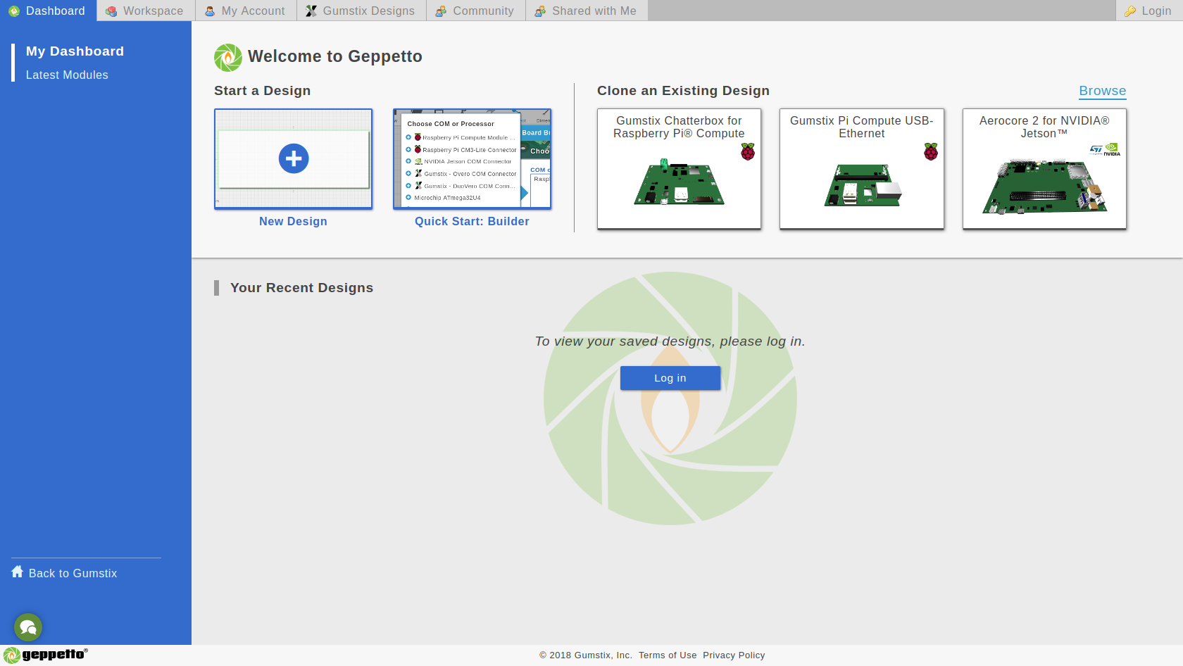
- Start from Scratch - With New Design, you're starting from an empty board where you have the option to drag modules into the board.
- Start from Builder - With Quick Start: Builder, you're presented with a list of categories and modules which you can select from. Then, Builder will add it to the board for you.
- Start from Template - With Clone an Existing Design, Geppetto will make a copy of a design by a Gumstix engineer which you can start your board with.
Moreover, the Dashboard contains a list of Latest Modules we released to the public in Geppetto.
Board Builder
It is one of the easiest ways to start a design in Geppetto. You just choose and select from a list of functionalities, click a button and the modules will be on your board.
The Geppetto Board Builder is one of the ways to start a Geppetto design.
How to use the Board Builder?
1. Choose functionalities or modules
Select the group you want on the board (e.g. COM or Processor). Board Builder will suggest a list of COM or Processor you can choose from on the left box. If you don't find what you need, use the Search functionality.
2. Click the [Start Build] button.
Board Builder will add and position your modules on the board.
3. Add Power
Board Builder also includes a power suggestion phase. You will enable this feature by following the on-screen prompt after the modules has been added.
4. Review and Finalize
Once you're finished with steps 1-3, you will have a board that's ready for your review and finalization.
Workspace Overview
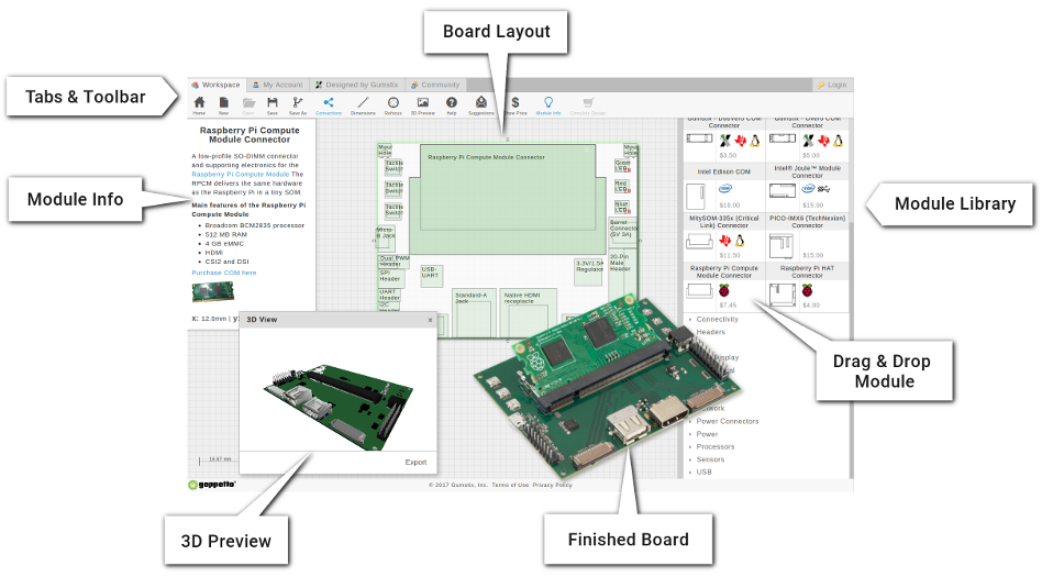
The Geppetto workspace contains all the tools to create a board
Basic Functions
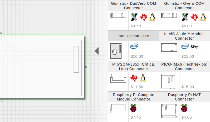
Drag and Drop
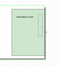
Find modules from the righthand library. Modules are functional blocks that offer a specific feature, such as power, sensors, connectors, and more. To add a module, simply drag and drop its graphic onto your board.
Reposition
Drag modules with your mouse to position as desired. For more precise placement, you can nudge the module with your keyboard's arrow keys. You should keep modules within the board boundary, and in their own space (ie. not overlapping with another module).
Connect
To connect a module, hover over it and and click the requirement flags that appear. Flags allow you to establish dependencies, including power requirements, between specific modules.
Board Resize and Corner Radius
To increase the size of the board, you can drag the edge of the board to the size you need. You can also use Dimension Mode and More Controls as described further below.
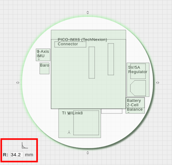
Moreover, if you want a board with radius on the edge, you can drag the lower-left edge of the board or adjust the radius.
Steps to Connect Modules
Color-coded requirement flags will display when you hover over a module. The flag color will indicate what needs to be done.

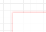
Connect a red requirement flag
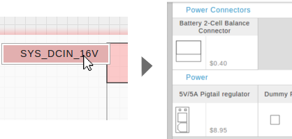
A red flag means that its dependency needs to be fulfilled by a new module from the library. Clicking this flag will make the module library automatically display matching options. Any of these options will fulfill the requirement.
When you add a valid module to your board, the red flag should detect it and turn yellow. You can now connect those two modules via their flags.
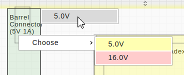
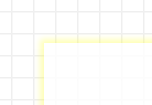
Connect a yellow requirement flag
A yellow flag means that another module on your board can fulfill its requirement.
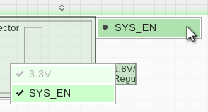
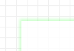
A connection is complete when the flag turns green. You can check where the module is connected by clicking this flag.
Disconnecting a module

The requirement flag should now become yellow, meaning it has disconnected.
Additional Module Controls
Right click on Work Space
When you click on a blank space on the board or outside the board in the work space, these options will appear:
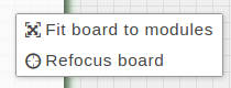
- Fit board to modules: This automatically resizes the board to enclose all modules in the Work space.
- Refocus board: If you lose sight of your board, re-center it here.
Click on Module
When you click on a module on the board, these options will appear:
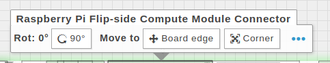
- 90°: This rotates the module 90 degrees counter clockwise.
- Board edge: This moves the module to the closest edge of the board.
- Corner: This moves the module to the closest corner of the board.
Double click on Module
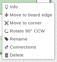
When you click a module again (double click), these options will appear:
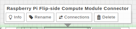
- Info: This provides more information about the module.
- Rename: This allows you to rename the module.
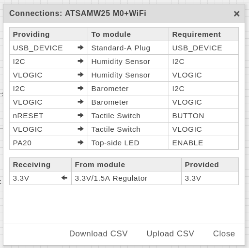
- Connections: This allows you to view, download, and upload connections of any given module.

- Delete: This will remove the module from the board.
Right click on Module
When you right click a module, all the options described in 2 and 3 will also be available.
Color Indicators
Colors indicate the status of your board and modules. Find explanations of each status below.
Module Color

Red
A dependency or requirement is missing from the board.

Yellow
Some connections have not been met, but can be satisfied by an existing module on the board.
Green
All dependencies have been met.
Module Outline
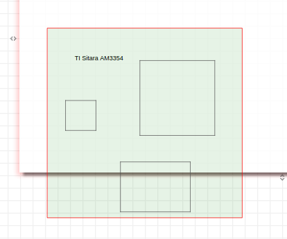
Red
The module cannot be placed here. Placement can be invalid if it is off the board, or overlapping with another module.
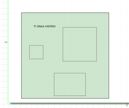
Black / Gray
The module can be physically placed here.
Board Outline
Red
The board is incomplete. Either the module is not properly placed within the board, a dependency is missing from the board, or both.
Yellow
There are unresolved connections between the modules on the board.
Green
All connections and dependencies have been met. The board is ready to be submitted for verification.
Toolbar

The toolbar offers the following functionalities, and more:
New: Start a new design.
Open: Browse and open your saved designs.
Save / Save As: Save your design into the My Account tab (requires an account).
Share: Share your design to colleagues to give them view access to your open design.
Builder: Opens Board Builder mode.
Find Power: Calculates power required based on the module on your board and adds what you selected.
Connect: A mode allowing you to view and create connections between modules.
Dimensions: A mode allowing you to take measurements.
*For more information about Connections and Dimensions, see Modes.
Refocus: If you lose sight of your board, re-center it here.
Help: View a quick tip slideshow.
Price: Get a cost estimate for your working design.
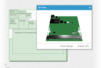
3D View: View your board as a to-scale 3D model.
Power: View a power calculation of your open design.
Download: Opens a window to enable download of Autodoc and AutoBSP.
- Autodoc: Generate a document about the open design.
- AutoBSP: Generate a board support package (BSP) specific to the open design.
Validate: Create a product page for your design (requires a store account). You can choose to submit your design for manufacturing from here.
Modes
Connections mode
Allows the requirement flags to appear, which represent the connections that are necessary for a module on the board. You can only connect modules while this mode is toggled on.
Please note that Connections mode disables Dimensions mode, and vice versa.
Dimensions mode
Allows you to control your board size, set the distance between the edge of the board and a module, or the distance between two modules.
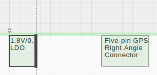
Steps to set dimensions
First ensure that Dimensions mode is on. Then, hover over the edge of the area to be measured until you see a dashed line.
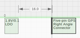
Your dimension should now appear. Geppetto recognizes measurements in increments of 0.5mm. You can input a value to adjust the distance, and right-click to lock the dimension. Lastly, you can also use this mode to view the static size of any module.
Tabs: My Account, Designed in Gumstix, Community, and Shared with Me

Besides the workspace, other tabs in the top bar offer extra functionalities:
My Account
You can sign in via your Google or Yahoo account, or use your e-mail address to create a Geppetto account. Once logged in, your saved designs will display here.
Also find toggles to change your theme colour to blue or black.
Designed by Gumstix
The Designed by Gumstix tab shows various boards sold by Gumstix and other boards designed by Gumstix Engineers. You can clone these boards and modify them to your design specifications.
Community
In the community tab, you can see designs shared by others in the Geppetto community. You can clone a board from here, or make a design based on another. Sharing designs is optional as part of the save process.
Shared with Me
In the shared with me tab, you can see designs shared by colleagues and friends only available to you. You can clone a board from here, or make a design based on it. Sharing designs is optional.